Baseline Design
The modeling done identifies a number of high level trends and provides some concrete baseline numbers for the hyperloop concept. For the most part, the ideas and numbers given in the original hyperloop proposal hold up using this analysis. However, the data shows that there are two major changes to the design that need to be considered.
- The tube will need to be significantly larger than the original proposal. In the original proposal, the tube was sized with a diameter 2.23 meters. However, it appears that it will need to have a diameter closer to 4 meters.
- On-board water based intercoolers are impractical due to volume and weight constraints. This may prove to be a non-issue since temperature rise due to compression is less significant than originally estimated and only leads to a modest rise in steady-state tube temperature. Assuming the tube was left uncovered, the heat rate from solar radiation would be an order of magnitude larger than the heat rate added from pod compression systems. Further assuming a 90 degF day, radiation and convection out of the tube would lead to a manageable steady state tube wall temperature of 120 degF.
Tube Diameter
The hyperloop pod travels through a fixed diameter tube. As it travels, it must displace air around itself. The displaced air moves past the pod with a relative velocity equal to the travel speed of the pod and must fit into the area between the pod and the tube wall. If you assume a circular cross section for the pod, then the area for the air to travel through is given by
Given the conditions in the tube, we know the density of air to be 0.00118 \(\frac{kg}{m^3}\). The mass flow rate of the air bypassing the pod is then given by
Since \(\rho_{air}\) and \(A_{tube}\) are both constant for given tube size and pressure, mass flow rate grows linearly with the velocity of the pod.
For any given flow there is a physical limitation to how the amount of flow you can pass through a given area. The maximum flow rate occurs when the velocity reaches Mach 1. For the hyperloop concept, all the air must fit through the area between the pod and the tube, called \(A_{bypass}\). When the air going through \(A_{bypass}\) reaches Mach 1, no additional flow can pass through.
If the required \(\dot{W}_{bypass}\) exceeds \(\dot{W}_{limit}\), then the pod will act like a piston in a tube and start the increase the air pressure in front of it and lower the pressure behind it. For the baseline hyperloop design, the limit speed is around 120 \(\frac{m}{s}\), or Mach .3, as shown in the figure below in the blue lines. The limit is reached when the required tube mass flow equals the kantrowitz limit flow. The value of this limit speed is strongly dependent on the ratio of the pod diameter to the tube diameter.
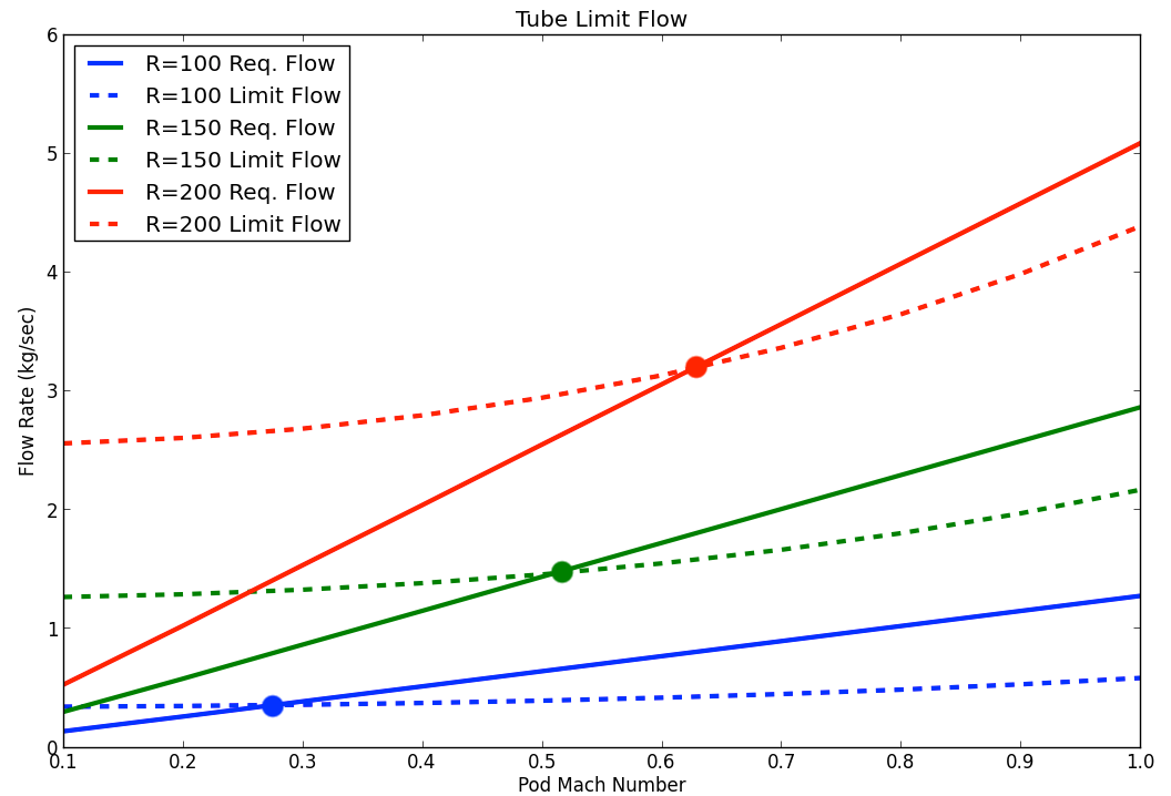
Hyperloop speed limits as a function of tube radius
Such low speeds would not allow the hyperloop concept to significantly reduce travel times between Los Angeles and San Francisco. To reach higher speeds, a compression system is needed to help push additional air around the pod to enable higher travel speeds. The amount of air that the compression system needs to move is equal to the difference between the required tube flow (the solid lines) and the limit (the dashed lines). As speed increases, the flow demands on the compression system increase as well.
The challenge is that when you increase the flow demands on the compression system, you also force the pod diameter to grow in order to handle the increased flow. So traveling faster means that the mass flow requirements grow, which drives the pod diameter up, which further increase the mass flow requirements. The only way to damp out this cycle is to allow the tube diameter to grow as you increase the maximum velocity. The model set up here converges on the minimal possible tube diameter, given a desired pod Mach number.
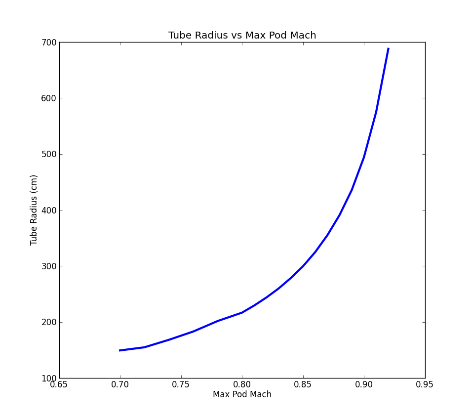
The data shows that above Mach .85, the minimum allowable tube size gets very sensitive to pod travel speed. This indicates that Mach numbers much higher than about .9 are likely not feasible. Even at a Mach .8, the tube diameter still needs to be around 4 meters. This is twice the size considered in the original proposal. At Mach .8 the travel time is around 45 minutes. Although this performance is less than described in the original proposal, it still represents an improvement over what can be achieved with a high speed rail.
Capsule Cooling Requirements
The limits and requirements of a hypothtical on-board heat exchanger can be estimated with a straightforward energy balance. The effectiveness of a heat exchanger can be described as the ratio of actual heat transfer over the maximum possible heat transfer. This can be written mathematically as,
where \({Q}_{max} = (T_{hot,in} - T_{cold,in}) {\big[ \dot{m}_{fluid} C_{p,fluid} \big]}_{lowest}\) with whichever fluid has the lowest product of \(\dot{m}_{fluid} C_{p,fluid}\)
In order to satisfy the energy balance \({Q}_{released} = {Q}_{absorbed}\) , the following must be true,
where the \(T_{out}\) of each fluid is unknown. With assumed massflow rates and initial temperatures, a valid combination of \(T_{out}\)‘s of each fluid can be found through solver iteration. Valid effectiveness levels for heat exchangers can be determined based on the E- NTU method..
The effectiveness for a counter flow heat exchanger with a Cmin/Cmax of ~0.25 was chosen
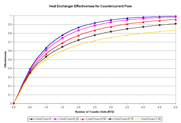
Image from http://www.cheresources.com/content/articles/heat-transfer/heat-exchanger-effectiveness
The following conditions satisfied an energy balance with an assumed effectiveness of 0.9765, and the proposed requirement to cool the air completely down to inlet temperatures.
| Fluid | Cp | \({T}_{in}\) | \({T}_{out}\) | \(\dot{m}\) | Q kJ/s | Q max |
|---|---|---|---|---|---|---|
| Air | 1.006 kJ/kg-K | 791 K | 300 K | 0.49 kg/s | -242 | 247.9 |
| Water | 4.186 kJ/kg-K | 288.15 K | 416.6 K | 0.45 kg/s | 242 | 247.9 |
With a 35 minute trip, \(0.45 kg/s * 60 s/min * 35 min = 945 kg\) of standard temperature/pressure water would need to be carried with appropriate sized steam tanks. This doesn’t even account for the second stage heat exchanger, making the system nearly infeasible with water and unpressurized tanks. Various systems involving alternate coolants such as liquid air or pressurized tanks could be explored.
Further discussion of heat exchanger sizing and tube equilibrium temperature can be found in the Tube Temperature section of the ‘Subsystem Modeling Theory’ chapter of the docs.
Sensitivity

Hyperloop speed limits as a function of tube radius