Model Layout
The model is broken down into 5 major sub-systems:
- Compression System (compress): Performance and power consumption of the compressors
- Mission Analysis (mission): Estimate of travel time
- Pod Geometry (pod): Physical Dimensions and calculations that depend on them
- Tube Flow Limitations (flow_limit): Pod speed limitations based on choked flow restrictions between the pod and the tube
- Tube Wall Temperature (tube_wall_temp): Equilibrium temperature of the tube wall
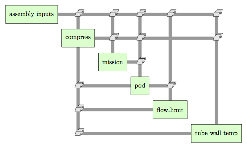
The overall layout of the hyperloop assembly and the connections between the components.
The compression system and pod geometry sub-systems are further broken down into sub assemblies.
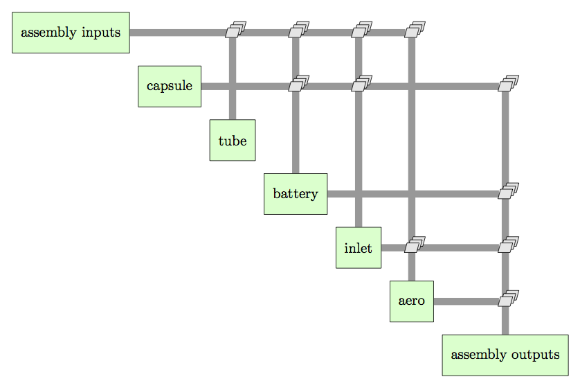
The expanded layout of the pod sub-assembly.
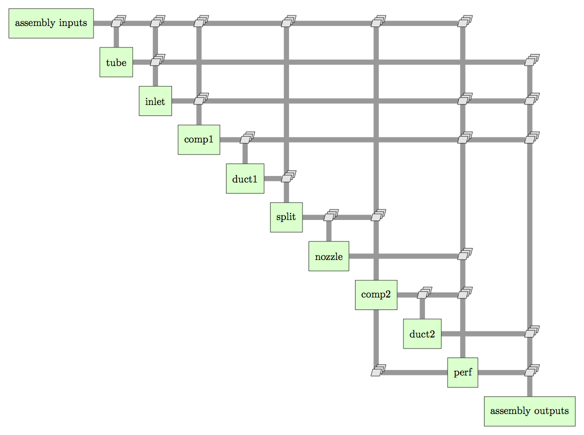
The expanded layout of the pod sub-assembly.
Inputs and Outputs
Note
Before describing the I/O of the model, note that this list represents the current state of the model. In its current form, this model is far from complete and as new analyses are added additional design variables and couplings will need to be added to this list.
Design Variables
The model has the following design variables:
| Variable | Description | Units | Baseline Value | Min. | Max. |
|---|---|---|---|---|---|
| Mach_bypass | Mach number of the air traveling around the pod | .95 | .5 | .98 | |
| Mach_pod_max | Maximum travel Mach number of the pod | .9 | .5 | .98 | |
| Mach_c1_in | Mach number of the air at the back of the inlet | .6 | .5 | .8 | |
| Ps_tube | Static pressure of the air in the tube | Pa | 99 | 99 | 500 |
| c1_PR_des | First compressor pressure ratio | 12.47 | 10 | 25 |
Model Parameters
These values are free for the user to set, but are not intended for the optimizer.
| Variable | Description | Units | Baseline Value | Min. | Max. |
| pwr_marg | Safety factor applied to the power requirement for the pod | .3 | 0 | 2 | |
| solar_heating_factor | Fraction of solar radiation to consider in tube temperature | .7 | 0 | 1 | |
| tube_length | Length of the tube | m | 563270 | N/A | N/A |
| n_rows | Number of rows of seats in the passenger capsule | 14 | |||
| length_row | Length alloted to each row of seats | cm | 150 | 120 | 200 |
| coef_drag | Drag coefficient for the pod | 2 | .6 | 2.5 | |
| hub_to_tip | Ratio of hub radius to tip radius for the first compressor | .4 | .2 | .6 |
Constraints and State Variables
The hyperloop system presents a multidisciplinary design problem. The cyclic connections in the above figure represent the coupling relationships between the different sub-systems. These couplings enforce a set of equality constraints that must be satisfied for any valid hyperloop design. For constraints 1 and 4, a multiplier has been applied to the constraint to scale it for improved numerical convergence.
- 0.01*(compress.W\_in - flow\_limit.W_excess) = 0
- compress.Ps\_bearing\_residual = 0
- tube\_wall\_temp.ss\_temp\_residual = 0
- 0.01*(pod.area\_compressor\_bypass - compress.area\_c1\_out) = 0
The model has a set of state variables that are varied to satisfy the constraints. State variables 3 and 4 are given as a list of variables. These are lists represent linked variables. They are treated as a single variable for the purposes of converging the model, but remain distinct variables in the model.
- compress.W_in
- compress.c2_PR_des
- (compress.Ts_tube,flow_limit.Ts_tube,tube_wall_temp.temp_boundary)
- (flow_limit.radius_tube, pod.radius_tube_inner)
Outputs
There are a number of output values that are of interest
- Overall pod radius: pod.radius_inlet_outer
- Total mass flow through the compression system: compress.W_in
- Total power required to drive the compression system: compress.pwr_req
- Total energy needed to power the compression system for one trip: mission.energy
- Travel time for one trip: mission.time
- Maximum speed: compress.speed_max
- Equilibrium tube temperature: tube_wall_temp.temp
Note
For a more complete design process, the values of the design variables would be optimized to minimize a combination of total power consumption and travel time. However, the model does not currently calculate some key values needed to get a useful answer. In particular, the linear accelerator and vacuum pump power needs to be modeled before a design optimization can be attempted.
It should be noted that you can select designs that are not realistic, particularly with respect to pod.radius_inlet_outer. There is a strong relationship between Mach_pod_max and the pod.radius_inlet_outer. If you select a high Mach_pod_max (Above .8), you may find that the radius has shrunk below what is physically feasible without significant design changes.